Furnace Control Cable Routing: Avoiding Kinks and Interference
What furnace control cables are and why routing matters
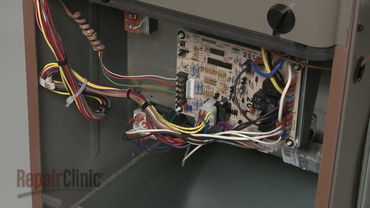
Control cables are the low-voltage and signal conductors that connect your thermostat, limit switches, pressure switches, gas valve, and furnace hose tube fitting parts control board. On modern furnaces and air handlers, these cables carry commands that start ignition, modulate gas burner control valve parts, stage the blower, and coordinate safety interlocks. Good routing protects these conductors from abrasion, electrical noise, and heat, and it keeps panels serviceable. Poor routing leads to intermittent lockouts, nuisance trips, short cycling, and scorched insulation that can spiral into expensive furnace repair parts. OEM furnace control cable parts, ties, grommets, and brackets are designed around the chassis geometry and service clearances, which is why using furnace bracket flange parts and furnace panel parts that match your model pays off over the long term.
I have lost count of the service calls where a furnace wouldn’t stay lit because a thermostat lead was pinched behind a door panel, or a pressure switch wire rubbed through on a sheet-metal edge. Cable management is not glamorous, but it’s often the most cost-effective “repair” you can make. Treat it like part of combustion safety, because it is.
Control cable routing fundamentals inside gas, electric, and oil furnaces
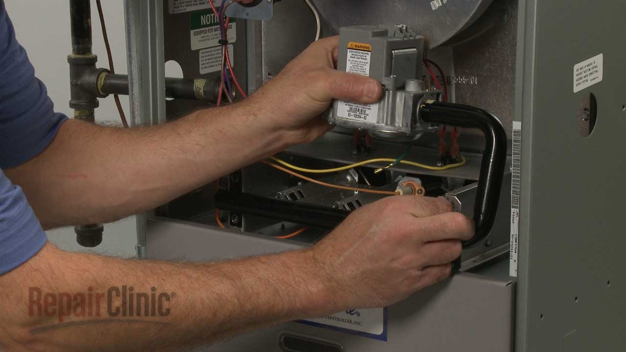
Every furnace type has its own hazards for control conductors. Gas furnaces concentrate heat around the burner vestibule and the ignition assembly, so keep wiring clear of furnace gas burner control valve parts, igniter brackets, and hot surfaces. Use high-temp furnace insulation parts and fiberglass sleeves near the burner compartment. Electric furnaces create broad radiant heat near furnace heating element parts, which means route cables along the chassis rails, then cross perpendicularly at the shortest path using edge grommets. Oil furnaces vibrate more, so strain relief at the blower deck and cabinet penetrations matters, and you may need extra furnace fastener parts and adhesive-backed anchors to tame movement.
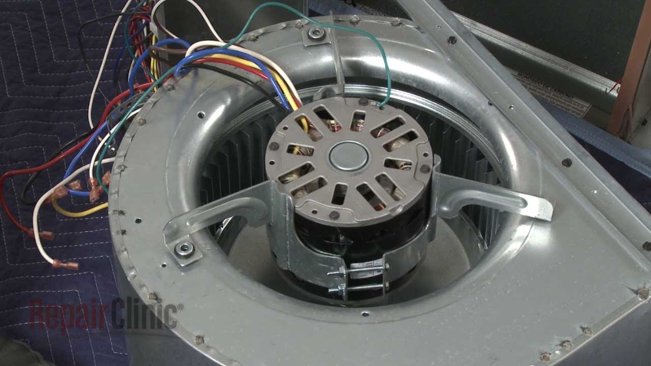
Regardless of fuel, follow the three C’s: clearance, clamping, and continuity. Maintain at least a finger’s width of clearance from blower wheels, belts, and rotating furnace motor parts. Use clamps, wire saddles, or furnace bracket flange parts at intervals of roughly 8 to 12 inches, closer where vibration is high. Then ensure continuity of protective measures: every sharp edge should have a bushing, every panel cutout a grommet, and every service loop anchored so it doesn’t droop into the furnace blower wheel fan blade parts. If your cabinet includes factory tie points on furnace chassis parts, use them, not the nearest screw you can find.
Common routing mistakes that create intermittent faults
Kinks are the obvious enemy. A tight bend near a spade terminal may not break a conductor immediately, but vibration will finish the job. Give every bend a radius at least three times the cable diameter. Avoid zip-tying a cable so tightly that jacket deformation is visible. And never rely on a single tie to reroute multiple circuits across a hinge axis, because repeated door movement will fatigue the copper.
Interference can be magnetic, electric, or mechanical. Running thermostat conductors alongside line-voltage feeds or inducer motor leads can induce noise that confuses the furnace circuit board timer parts and ignition controls. Keep low-voltage harnesses separated from high-voltage by at least a couple of inches, and cross at right angles when paths must intersect. Mechanically, watch for hidden snags. The inner lips of furnace door parts, sliding furnace panel parts, and even a protruding screw on the furnace grille kickplate parts can act like a wire stripper over time. I’ve seen pressure switch hoses routed below a blower deck so the blower negative pressure collapsed the tube at high speed, mimicking a failed switch. Furnace hose tube fitting parts should arc gently and avoid long horizontal runs where condensate can pool.
Planning a clean harness layout, step by step
Start with a map. Trace each circuit with your finger from the control board to its device: inducer, flame sensor, igniter, blower, gas valve, limit, rollout switch, and thermostat. Count the number of crossing points, then rearrange the order of runs so each has the straightest path with the fewest crossings. Leave a modest service loop at devices that get replaced most often, such as furnace igniter parts and furnace capacitor parts, but anchor the loop so it cannot fall into the blower housing or touch the heat exchanger.
Respect service access. Panels should install without pinching wires, which means test-fit the door after routing and look for light marks on the insulation that reveal contact points. Where a panel does rub slightly, stick on a small square of high-temp tape or apply a grommet edge, sometimes available as part of furnace gasket seal parts. If you need to join two harness sections, use crimp connectors rated for the temperature zone and add a short length of heat-shrink. If the factory uses a cable color code, match it. It saves time the next time a tech opens the cabinet.
Materials and small parts that make or break cable management
Factories often supply stick-on anchors, edge grommets, and metal tabs that were chosen for the cabinet’s temperature zones. When retrofitting, choose parts with the same ratings. High-temp zip ties retain strength above 200 degrees Fahrenheit. Edge grommets protect pass-throughs where a harness crosses furnace panel parts or furnace door parts. Where anchors fail to stick on dusty or painted sheet metal, clean with a solvent, then use furnace adhesive parts designed for HVAC panels. If your harness passes near a blower shaft, add a fixed tie to a hole or flange on the furnace chassis parts, then a second floating tie a couple of inches away to act as a fail-safe if the first breaks.
For electrical immunity, braided sleeving or foil-shielded cable can be helpful around variable-speed blower control leads. Keep such shields grounded per the manufacturer’s instructions. If buzzing from contactors or alternator-style modules kicks noise into neighboring circuits, reroute low-voltage runs an inch or two farther from those sources. Small shifts often solve mysterious lockouts that would otherwise have you pricing out furnace ignition controls parts you do not need.
When to re-terminate, replace, or upgrade the control cable
If you see green corrosion, rigid jacket sections, or flaking insulation, re-terminate or replace that section. OEM harnesses often come pre-cut with device leads, Frigidaire furnace parts but you can fabricate clean one-for-one replacements if you match gauge, temperature rating, and connector type. Resist the temptation to twist-and-tape. Use proper crimp spades or ferrules and verify pull strength. For thermostats, use stranded conductors for flexibility inside the cabinet. If a run must cross a hinge or door seam, move the hinge side to the short leg of the run and anchor both sides so movement is controlled.
Sometimes the best upgrade is not the wire, but the path. Add a short piece of cable channel along the cabinet’s vertical stanchion to keep wires flat and protected from furnace blower wheel fan blade parts. Replace worn grommets with fresh furnace gasket seal parts sized to the knockout. If your board lacks a dedicated strain relief, mount a small bracket using existing screw holes to avoid drilling near the heat exchanger. Small layout improvements can eliminate nuisance lockouts that look like control board failures.
Related parts that interact with control cables
While this article focuses on routing, you will frequently touch adjacent components. The furnace circuit board timer parts often sit at the hub of all low-voltage wiring, so inspect its header pins and ensure no conductor strands are frayed across terminals. Furnace fuse thermal fuse breaker parts protect those circuits; if a low-voltage fuse keeps blowing, look for chafed cable jackets inside the blower furnace handle parts deck. Furnace capacitor parts sit close to the blower motor wiring, and their leads can radiate noise into thermostat runs if bundled together. Keep them separated and secured to prevent humming from becoming interference.
On older units, furnace hinge parts and furnace latch parts may be bent, causing door panels to press harder on harnesses than the factory intended. Straighten or replace those hardware pieces to restore proper clearances. In tight closets, add protective edging where harnesses pass near furnace duct venting parts so sheet-metal vibration cannot saw through insulation. These small fixes build a robust installation where control signals remain stable season after season.
Brand nuances and service experience across common models
Carrier, Trane, Lennox, Rheem, and Goodman each route harnesses a little differently. Carrier and Bryant boards often mount near the blower deck, which tempts short, direct runs across moving parts. Keep those runs against the cabinet, then turn the corner down low. Trane variable-speed systems are sensitive to induced noise on the ECM control leads; keep thermostat and sensor runs away from blower motor harnesses. Lennox models with tight vestibules benefit from extra edge grommets at the burner access, because the door lip sits close to the hot surface igniter leads. Rheem and Ruud inducer sections can trap heat behind the burner shield, so add fiberglass sleeves on igniter and flame sensor leads that pass nearby. Goodman cabinets usually have generous tie points stamped into the furnace chassis parts; use them, and you rarely see rub-throughs later.
Whenever you are unsure how a specific brand intends the harness to run, check the schematic and the cabinet diagram included with furnace manuals care guides literature parts. The factory often shows intended tie points, grommet locations, and wire color routing that reduce conflicts with service access. That drawing is worth the five minutes it takes Duroguard furnace parts to study.
Quick field checklist for routing control cables without kinks or interference
- Maintain separation: low-voltage away from line-voltage and motor leads, crossing at right angles.
- Anchor every 8 to 12 inches and protect every edge with a grommet, bushing, or gasket strip.
- Use generous bend radii and leave anchored service loops only where replacements are routine.
- Test-fit doors and panels to verify zero pinch points, then run the system and listen for rubbing.
Sourcing the right OEM routing hardware and small parts
Finding the exact furnace control cable parts makes the job cleaner. OEM harness clips, bushings, and grommets match cabinet thickness and maintain the right compression so cables don’t rattle loose. If you need replacements, you can find a broad range of repair clinic furnace parts list, including routing components, across many brands. For boards, relays, and timers that sit at the center of the harness, see furnace circuit board and timer components. When blower leads and low-voltage runs must share a cabinet, fresh run capacitors and proper mounting help, and you can click here for furnace capacitors. If heat or abrasion is evident near panel edges or knockouts, fit new gasket and seal parts to protect the harness and restore panel fit.
FAQs: fast answers to common routing and control issues
Clear wiring paths solve many “mystery” faults. These brief answers point you in the right direction.
Why is my furnace short cycling after a thermostat upgrade?
Short cycling can result from induced noise or poor routing that causes voltage drop on the thermostat circuit. Keep low-voltage wires away from blower and inducer motor leads, avoid sharing a bundle with line-voltage, and tighten all spade connections at the furnace circuit board timer parts. Verify thermostat wire gauge and that the anticipator or cycle rate is set per the furnace manual.
Where should I route the hot surface igniter leads?
Run igniter leads along the coolest available path in the burner vestibule, furnace lighting light bulb parts protected by fiberglass sleeve if they pass within a couple of inches of the heat shield. Anchor to the furnace chassis parts, keep away from sharp burner brackets, and leave a small service loop that cannot sag into the flame path. Do not bundle with blower or inducer leads to avoid electrical noise.
How do I stop a control wire from getting pinched by the blower door?
Identify the pinch point by looking for jacket marks or by dusting the panel edge with chalk and reinstalling it. Reroute the wire along cabinet rails, add a stick-on anchor, and protect the crossing with a grommet or a strip from furnace gasket seal parts. If the door is warped, correct it by adjusting furnace hinge parts or replacing a bent latch.
My low-voltage fuse keeps blowing. Could routing be the cause?
Yes. Chafed conductors on sheet metal or moving parts are common culprits. Inspect harness sections near the blower deck, around the furnace blower wheel fan blade parts, and at panel cutouts. Replace damaged wire, add grommets, and keep low-voltage away from rotating parts. Always install the correct amp rating when replacing furnace fuse thermal fuse breaker parts.
Where can I find manuals and part numbers to match routing hardware to my model?
Schematics and cabinet diagrams are included with furnace manuals care guides literature parts. Many suppliers host PDF manuals by model number, which detail tie points, grommet types, and harness routing paths. Having the exact diagram prevents guesswork and ensures your repair aligns with OEM intent.
Furnace Parts – Reliable OEM solutions for clean, safe cable routing
Cable routing looks simple until you see what a pinch, a rub, or a little electrical noise does to a modern control board. The fix is not just tidying wires with a handful of zip ties. It is choosing the right path, protecting every edge, anchoring for vibration, and respecting heat zones. Use OEM furnace control cable parts, grommets, and bracket flange parts that fit your cabinet, keep low-voltage away from motor and line-voltage runs, and allow panels to slide on without stress. While you’re inside the cabinet, it often makes sense to refresh a tired run capacitor, a worn grommet, or a brittle connector, because those details are the difference between a furnace that hums through winter and one that throws a lockout on the coldest night.
If you need a starting point for sourcing, you can find control cable parts here and match them to your model number. Pair those with the right circuit board, capacitors, and gasket seals and you’ll have all the small, specific pieces that make a professional routing job last.